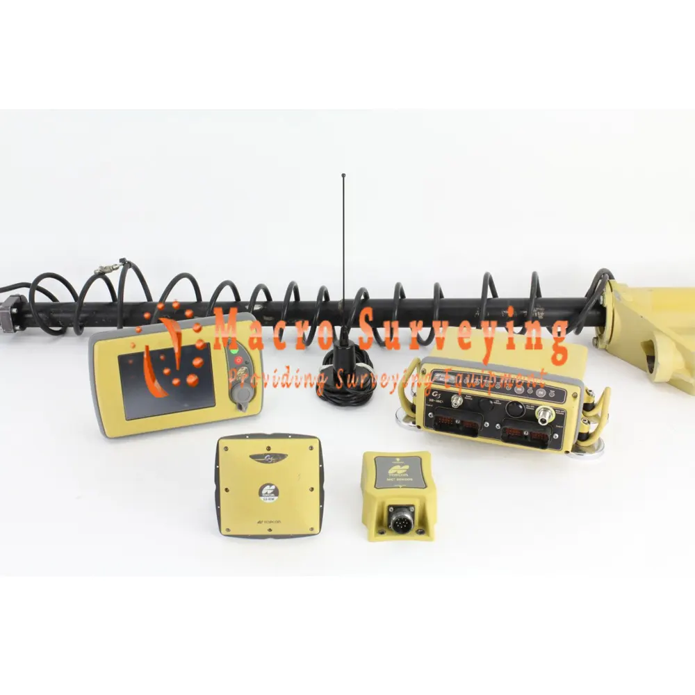
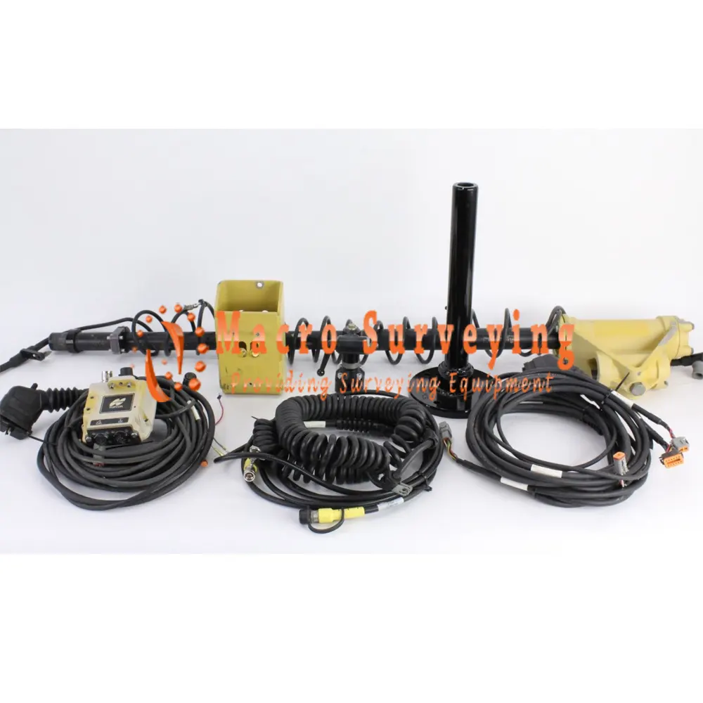
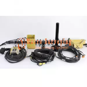
Topcon 3D-MC2 Full Dozer GPS Kit
Sell used Topcon 3D-MC2 Single Antenna Full Dozer Kit with MC-R3 UHF I, GX-60, GLONASS/GPS
Condition: Used

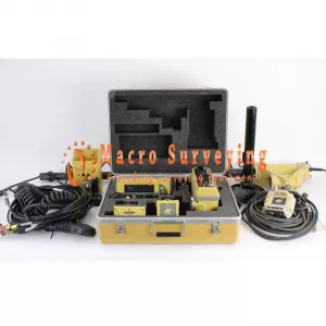


Topcon 3D-MC2 Full Dozer Hardware and Install Kit, and will work on multiple machines. These are all in great working condition, tested and guaranteed, There is a 30 days return and 90 days warranty included.
Topcon 3D-MC2 Full Dozer GPS Kit includes:
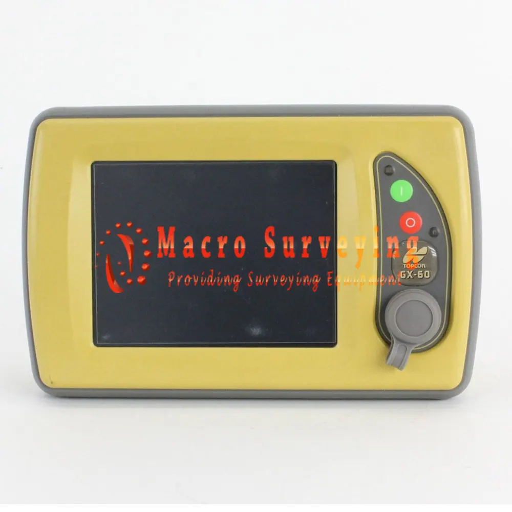
- Topcon GX-60 Display with Automatics Enabled
- 3DMC Version 12.1.327 Software
- Topcon MC-R3 Single Port Receiver with Mag Mount
- Topcon UHF 410-470 MHz Internal Radio
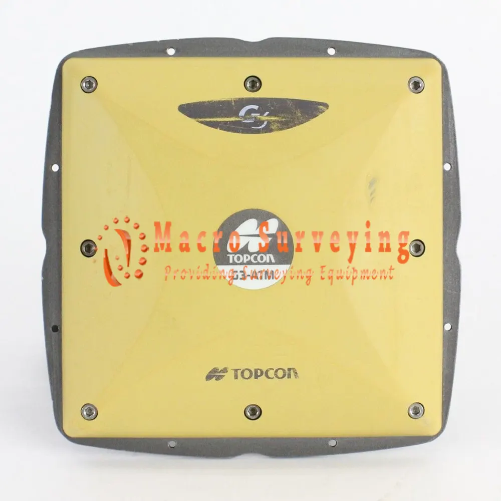
- Topcon G3-A1M Antenna with Mast Mount
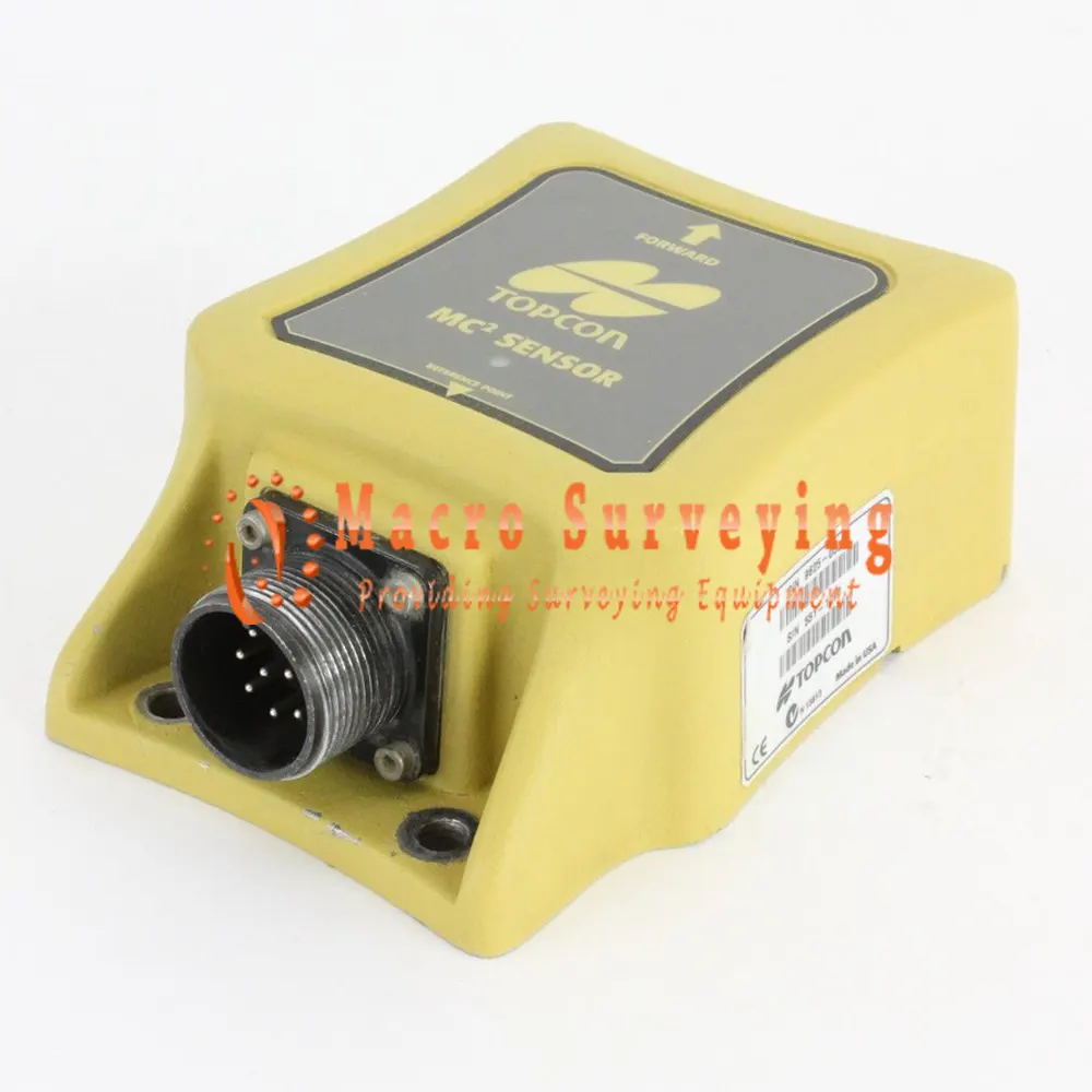
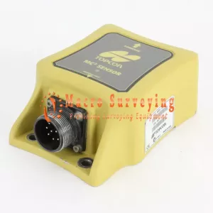
- Topcon MC2 Sensor with Coil Cable
- Topcon Full Dozer Install Kit
- Topcon Mast with Antenna Bracket
- Radio Antenna with Mag Mount
- Topcon Antenna Cable
- Topcon Transport Case
- 90 Day warranty
- 30 Day return
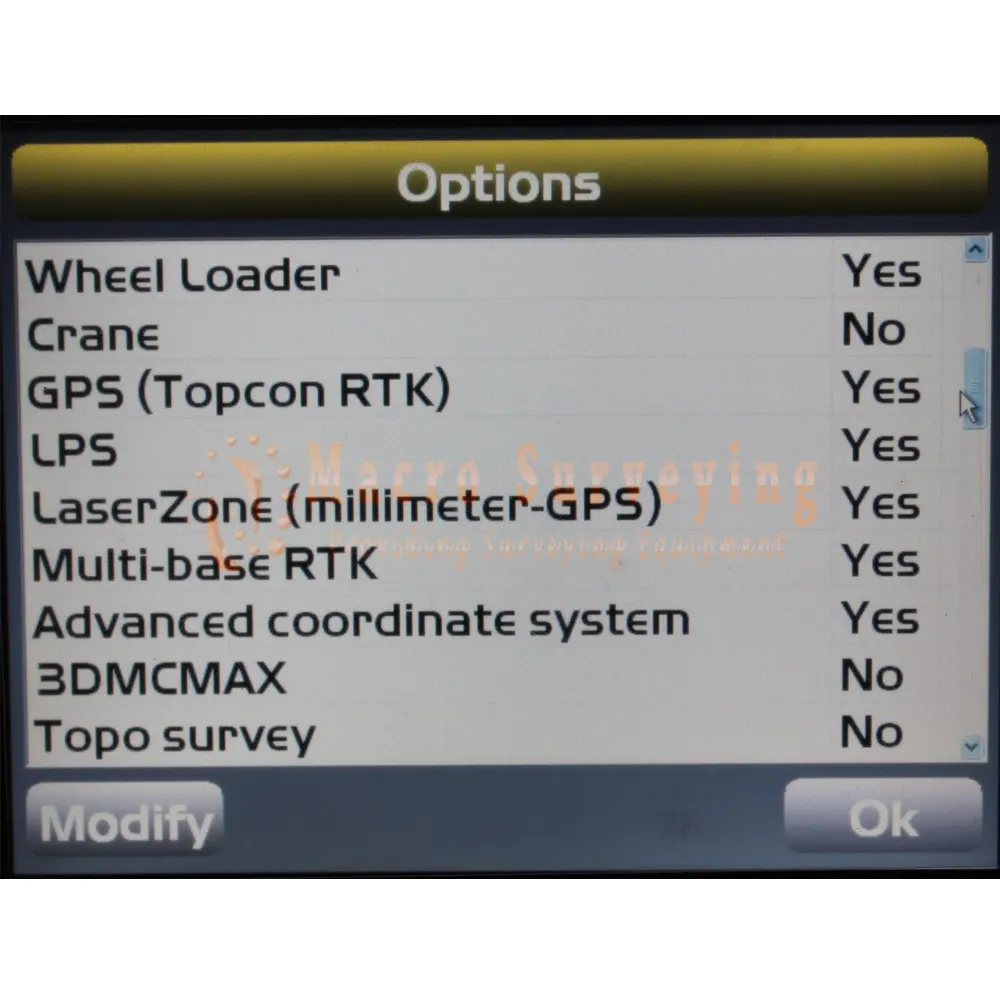
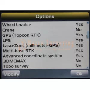
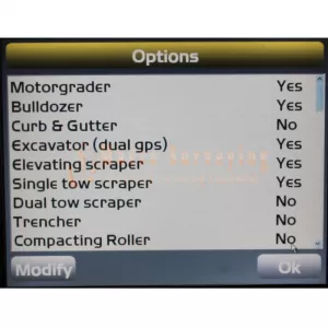
Enabled Options:
- GPS
- Whell loader
- LPS
- RTK
- Glonass
- Automatics
- MC2 Sensor
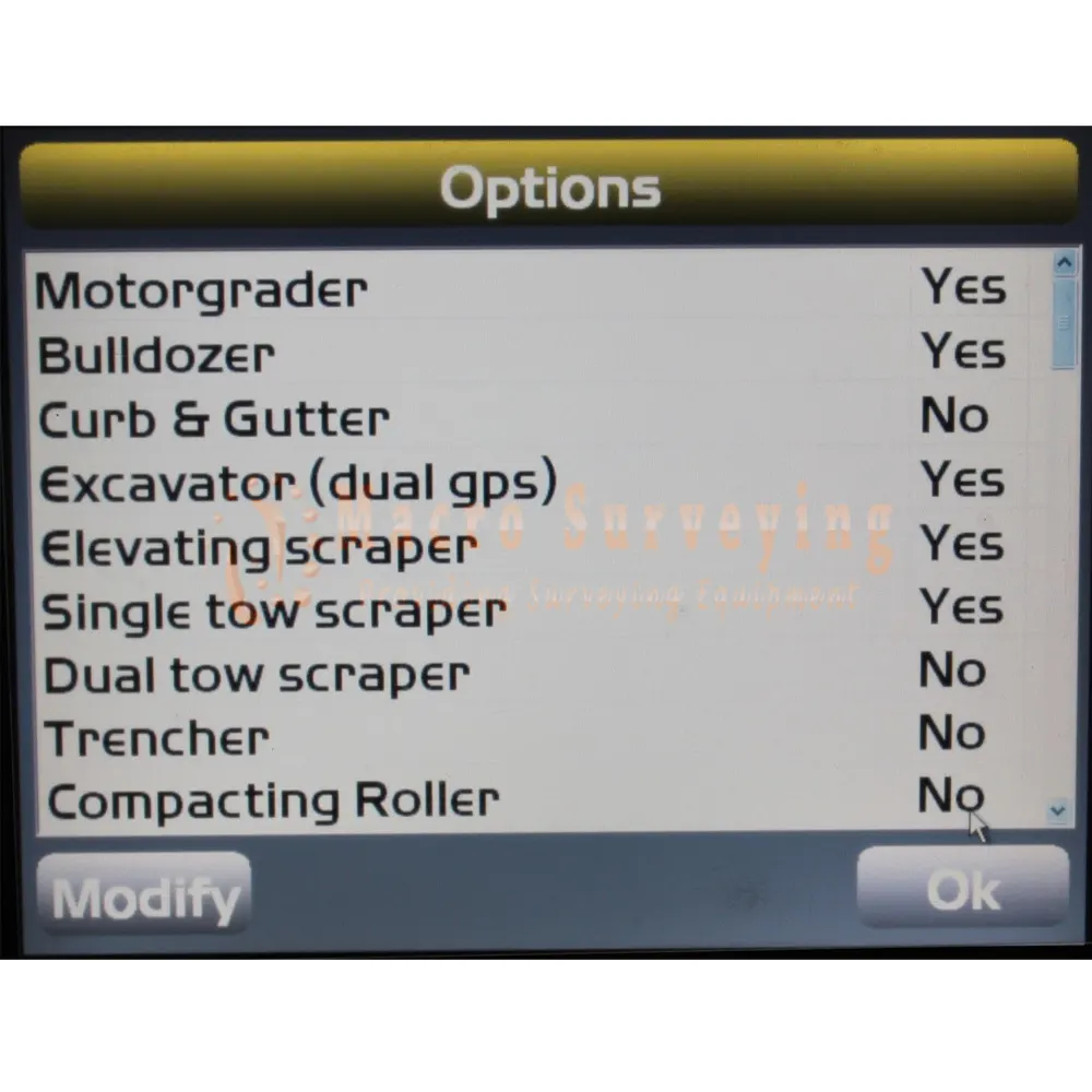
- Dozer
- Motorgrader
- Excavator
- Elevating scraper
- Single tow scraper
Topcon GX-60 Display with Automatics Enabled 3DMC Version 12.1.327 Software
The GX-60 graphical computer display was designed for rugged machine environments. Bluetooth, Ethernet, and USB ports are available for future wireless machine applications.
Features & Benefits
- The high-resolution, bright, color, touch screen display easily adapts to a variety of machine applications, providing the operator with easy-to-view graphical information.
- Bluetooth, Ethernet, and USB ports provide communication access between the control box and external devices (wireless or plug-n-play). Internal Blue tooth wireless technology provides scalability for future wireless machine applications. The USB port is accessible on the front of the control box providing quick access to save and download files, and to connect an external device (such as a USB keyboard or mouse).
- Adjustable side or rear mounting options secure the control box in the cab. The clamps provide easy6 attachment at the beginning of the day and easy removal for storage at the end of the day.
- All cables attach in the back and remove easily with quick-disconnect connectors.
- A internal battery pack prevents data loss in the event of power interruptions.
Topcon GX60 Spesification
| Physical | |
| Display Panel | 640x480 Color VGA, enhanced brightness with analog touchscreen |
| Housing | Cast aluminum |
| Audio | 1ea environmentally sealed speaker w/ 1.5 watt amp |
| Switches | 2 ea momentary pushbutton (power on / off) |
| Connectors | 2 ea 19 socket MIL-C-5015 cylindrical connectors Gold plated contacts, conductive anticorrosive plated housing |
| Cooling | 1ea internal processor fan |
| 1ea external housing fan | |
| Weight | 6 lbs. |
| Electrical | |
| Supply Voltage | 10-30VDC |
| Supply Current | 3A Typical operating current - Maximum at 10VDC input power, no peripheral equiptment 8A Maximum operating current |
| Switched Output Power | 5A Sensor/Conditioned output power |
| Ports | USB (2) |
| Ethernet - One port only routed to two connectors | |
| RS-485 | |
| RS-232 | |
| CAN(2) | |
| Digital inputs (2) | |
| Environmental | |
| Operating Temperature | -20°C to +60°C |
| Humidity | Mil Std 810D, method 506 |
| Shock Rating | 50G 11ms 1?2 sine wave each axis |
| Vibration Rating | 10-400Hz sweep 5G, 1 oct/min |
| 10-400Hz random 5G, 15 min each axis | |
| Salt Fog Test | 48 Hours |
Topcon MC-R3 Single Port Receiver
Topcon’s MC-R3 is developed specifically for machine control applications, the MC-R3 Controller combines the latest GNSS receiver technology, wireless modems, several communication port options, and System Five valve controller into one robust unit.
Features & Benefits
- G3 Tracking technology
- Network capable receiver with GSM / CDMA
- UHF & Spread Spectrum radio options
- LED indicators for satelite tracking and controller status
- Advance Multipath Reduction (AMR)
- In-band Interference Rejection (IBIR) option
- Compliance with CMR and RTCM industry standard
- Flash download capability (application code revisions in the field)
- System Five Controller
- Ethernet and RS-232 and RS-485 serial connection to GPS receivers and valve controller board
Topcon MC-R3 Specifications:
| Physical | |
| Housing | Powder-coated, cast aluminum |
| Connectors | 2 ea. DRC23-40P Deutsch high density connector, gold plated contacts, plastic housing, unique keyed |
| 2 ea. Type N for GPS (optional) | |
| 1 ea. RP-TNC for radio (optional) | |
| 1 ea. TNC for LPS (optional) | |
| Switches | Logic control: Hi = On, Low = Off |
| LEDs | CAN |
| Sensor | |
| Controller | |
| Auto | |
| Radio Modem | |
| Main GPS Receiver | |
| Aux GPS Receiver | |
| Cooling | Internal Fan |
| Weight | 7.5 lbs |
| Electrical | |
| Supply Voltage | 10-30 VDC |
| Supply Current | 3A typical operating current 18.5A Max 3mA at 24V typical leakage current 1.5mA at 12V |
| Emmissions | Applicable regulation: EN55022: 2006 30-230MHz 40.0dB (mV/m) Max at 10m 230-1000MHz 47.0dB (mV/m) Max at 10m |
| Immunity | Applicable regulation: EN55024: 1998 |
| A1: 2001/A2: 2003 | |
| ESD: +/-8KV RF: 80-1000MHz 3 V/m Fast transient: +/-.5KV capacitively coupled RF common mode: 3V 150kHz to 8MHz (80% 1kHz AM) | |
| Output Power | 10A max for sensors 8A max for valves 12V/500mA max for external radio modem |
| Ports | 1 ea. Topcon proprietary RS-485 port for sensors |
| 1 ea. RS-232 dedicated port for Graphic Managment Unit (GMU) | |
| 2 ea. RS-232 dedicated ports for Main and Aux GPS receivers | |
| 2 ea. RS-232 dedicated ports for mmGPS | |
| 1 ea. RS-232 dedicated port for external modem | |
| 2 ea. CAN ports 2 ea. Ethernet ports | |
| 1 ea. I2C port for Smart KnobTM | |
| 1 ea. SIM card (optional) - EDGE compatible | |
| GNSS | |
| Number of Channels | 144 |
| Signals | GPS, GLONASS, SBAS |
| Position Accuracy | RTK H: 10 mm + 1.0 ppm, V: 15 mm + 1.0 ppm |
| DGPS H: 0.4 m, V: 0.6 m | |
| Fast Static (L1+L2) H: 3 mm + 0.5 ppm, V: 5 mm + 0.5 ppm | |
| Environmental | |
| Operating Temperature | -20°C to +60°C |
| Ingress Protection | IP-66 |
| Shock Rating | 50G 11ms 1/2 sine wave each axis |
| Salt Spray Test | MIL-STD 810F |
| Vibration Rating | 10-400Hz sweep 5G RMS |
Topcon G3-A1M Antenna with Mast Mount
The G3-A1 is intended for high vibration uses, such as on the top of a machine control mast. The antennas have been tested to extreme vibration specifications and are recommended for the most rugged environments. Why risk placing an expensive electronic receiver at the top of a machine mast. This ruggedized antenna can be used with dozers, motor graders, scrapers, milling machines, and other systems. An optional ground plane can be easily attached to supplement the reduction of multipath signal interference.
- Rugged design
- GPS and GLONASS
- Vibration tested
- Optional Ground Plane
Topcon G3-A1M Specifications:
| Physical | |
| Antenna Connector | TNC female (G3-A1), N female (G3-A1M) |
| Mount | 5/8-11 thread |
| Dimensions | 141.6 x 141.6 mm (without Ground Plane) |
| Diameter | 179.4 mm (circumference, without Ground Plane) |
| 200 mm (with Ground Plane) | |
| 205 mm (with GP and anti-snow spherical dome | |
| Height | 53.7 mm (without anti-snow spherical dome) |
| 149.5 mm (with anti-snow spherical dome) | |
| Weight | 515 g (antenna without Ground Plane) |
| 185 g (Ground Plane) | |
| 700 g (antenna with Ground Plane) | |
| 195 g (anti-snow dome) | |
| 895 g (Antenna with GP and anti-snow dome) | |
| Operating Frequency Range | |
| L1 GPS/GLONASS | 1586.5 ± 25 MHz |
| L2 GPS/GLONASS | 1236 ± 20 MHz |
| L5 GPS | 1176 ± 12 MHz |
| Out of Band Rejection | |
| L1 | ± 100 MHz -30 dBc (typical) |
| L2 | ± 100 MHz -60 dBc (typical) |
| Gain, Noise Figure and VSWR | |
| LNA Gain | 30 dB (typical) |
| Gain at Zenith (90°) | GPS L1 6 dBic (minimum) |
| GPS L2 5.5 dBic (minimum) | |
| GPS L5 4 dBic (minimum) | |
| GLONASS L1 4.5 dBic (minimum) | |
| GLONASS L2 4 dBic (minimum) | |
| Gain Roll-Off (from Zenith to Horizon) | GPS L1 -12 dB |
| GPS L2 -13 dB | |
| GPS L5 -13 dB | |
| GLONASS L1 -12 dB | |
| GLONASS L2 -13 dB | |
| Noise Figure | 1.8 dB (typical) |
| VSWR | ≤ 2.0 : 1 |
| L1-L2 Differential Propagation Delay | 6 ns (maximum) |
| Nominal Impedance | 50 Ohms |
| Environmental
|
|
| Temperature | Operating: -50°C to 70°C; Storage: -55°C to 85°C |
| Water / Dust Rating | IPX5 IEC 60529 / IP6X IEC 60529 |
| Vibration | Category 20, Composite Wheeled/Tracked Machine Exposure, along each of 3 axes (Method 514.5, Table 514.5C-VII and Figure 514.5C-3) |
| Humidity | 95% |
| Shock | Humidity Along each of 3 axes (Method 516.4, Procedure I, Functional Shock, Table 516.5-II, Figures 516.5-10 - accelerative forces up to 40g (Method 507.4) |
| Salt Fog | 5% (Method 509.4) |
| Drop Test | Repeated drops of antenna with pole from the height of 2 m (the pole height) on asphaltic concrete surface. |
| RoHS Compliant | Yes |
| Power
|
|
| Input Voltage | 3 to 18 VDC |
| Power Consumption | 30 mA (typical) |